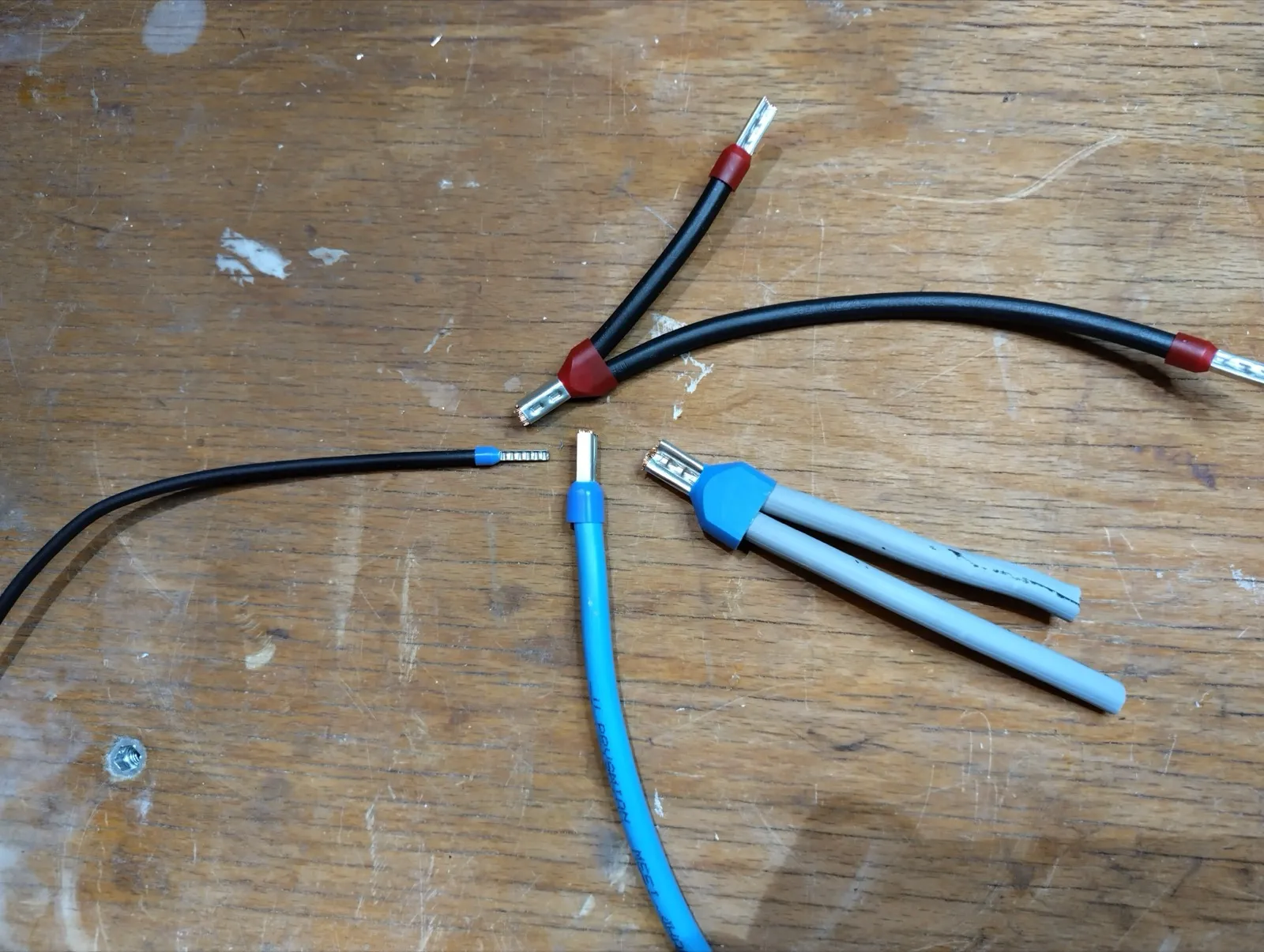
Crimping Twin Ferrules: 10 and 16 mm²
Why a standard ferrule tool gives up on twin ferrules at 10 mm² and up, and how to crimp 10 and 16 mm² TWIN cross-sections cleanly anyway.
I recently tried to crimp two 10 mm² conductors into a twin ferrule, and my usual crimping pliers simply wouldn’t close. The tool wasn’t bad. It’s built for standard ferrules up to 10 mm², not for the TWIN version at that size. This comes up whenever two conductors need to land in the same spring terminal or terminal block.
Why a twin ferrule crimps differently than a single one
With a single ferrule, the tool presses a round profile onto a round conductor. With a twin ferrule, two conductors sit side by side inside a ferrule that has an oval or rectangular cross-section instead. For both conductors to end up seated firmly, the crimp head actually has to match that different profile. A standard hexagonal or round profile only squeezes a TWIN ferrule at two points, leaving air gaps in between. That’s exactly where one of the two conductors will eventually work loose.
Why most crimping tools give up at 10 and 16 mm²
The typical hardware-store ferrule tool is built for single conductors up to 10 mm², and often covers TWIN only up to 2x6 mm², if at all. The reason is simple: two 10 mm² conductors side by side need more surface area and more force at the crimp head than a small hand lever can deliver. At 16 mm² TWIN, it only gets worse. Use the wrong tool here and you’ll either fail to close the ferrule properly, or deform it so unevenly that one conductor stays loose.
What you actually need for 10 and 16 mm² TWIN
Check the tool’s crimp chart to see whether TWIN cross-sections are listed at exactly the size you need. If it just says “0.5-10 mm²” with no TWIN or twin designation, the tool is meant for single conductors and isn’t rated for a double load, even if the ferrule physically fits between the jaws. For 10 and 16 mm² TWIN you need a tool system with interchangeable dies, not some generic single-hand pliers off the shelf.
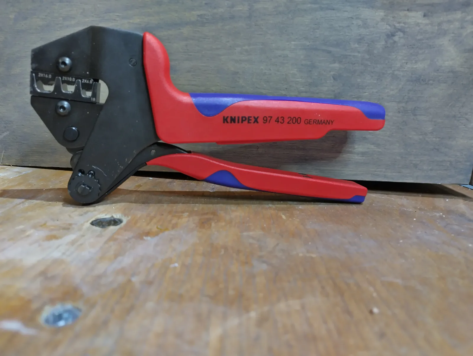
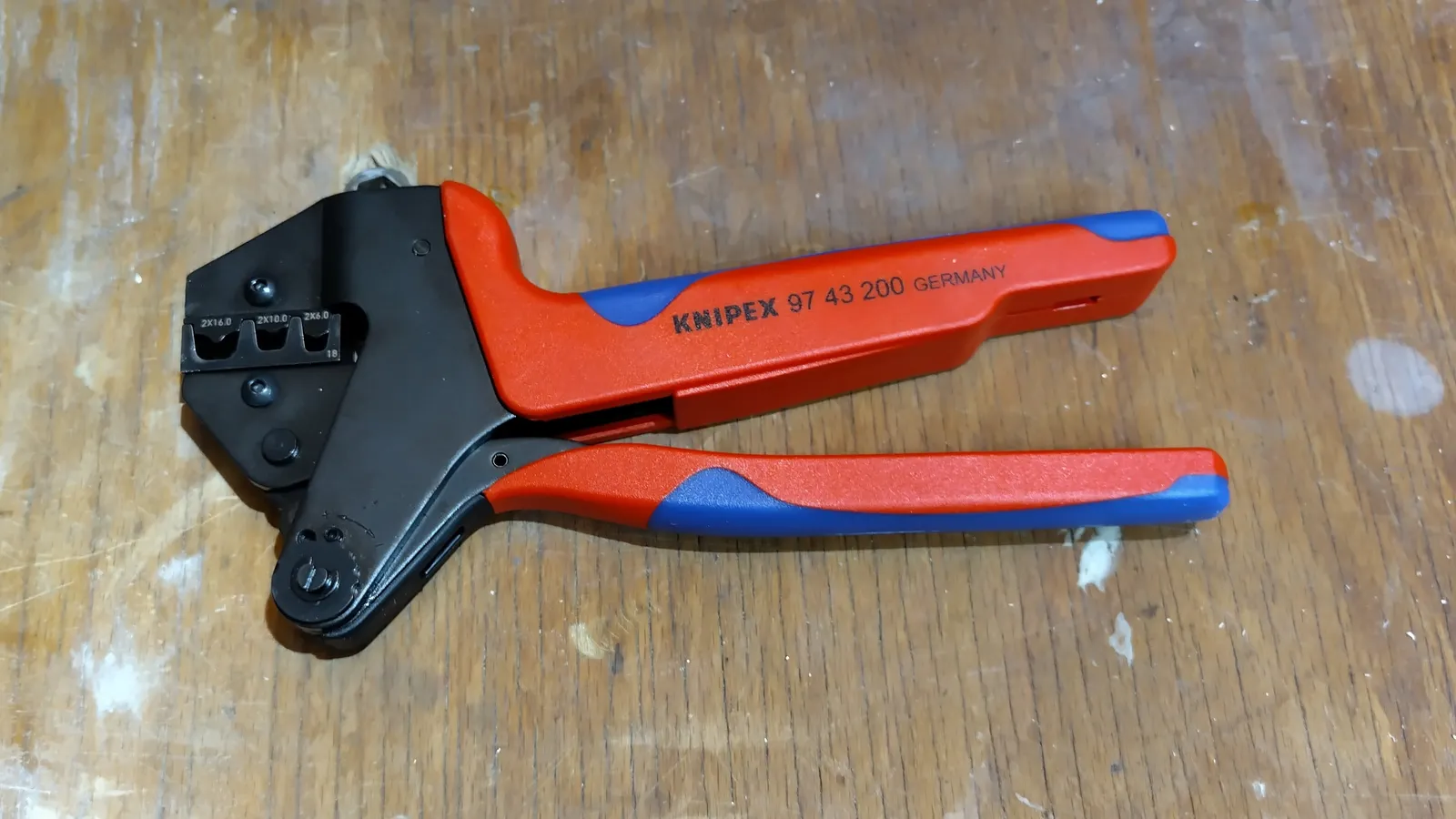
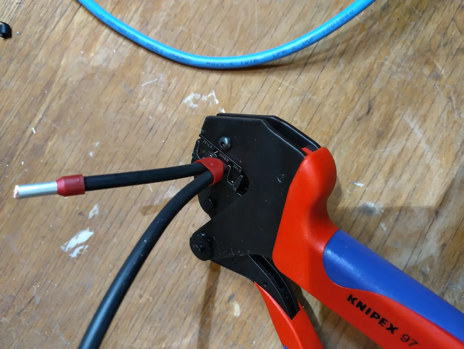
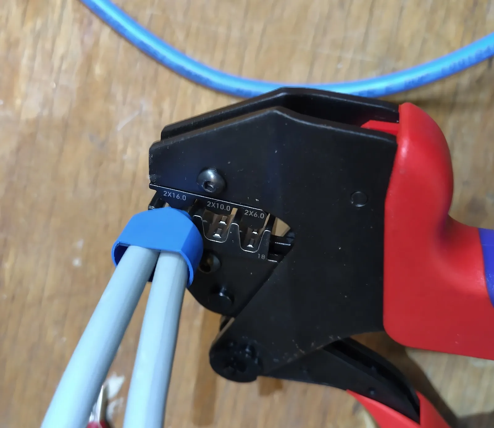
I use the Knipex 97 43 200 A crimping pliers together with the Knipex 97 49 18 crimp die for twin ferrules. The pliers themselves deliver plenty of force and leverage for larger cross-sections through the interchangeable head, and the die brings the right TWIN profile in the right size. Without that die, even the best pliers only press a round profile, and that’s no good for two conductors sitting side by side.
The dies you need
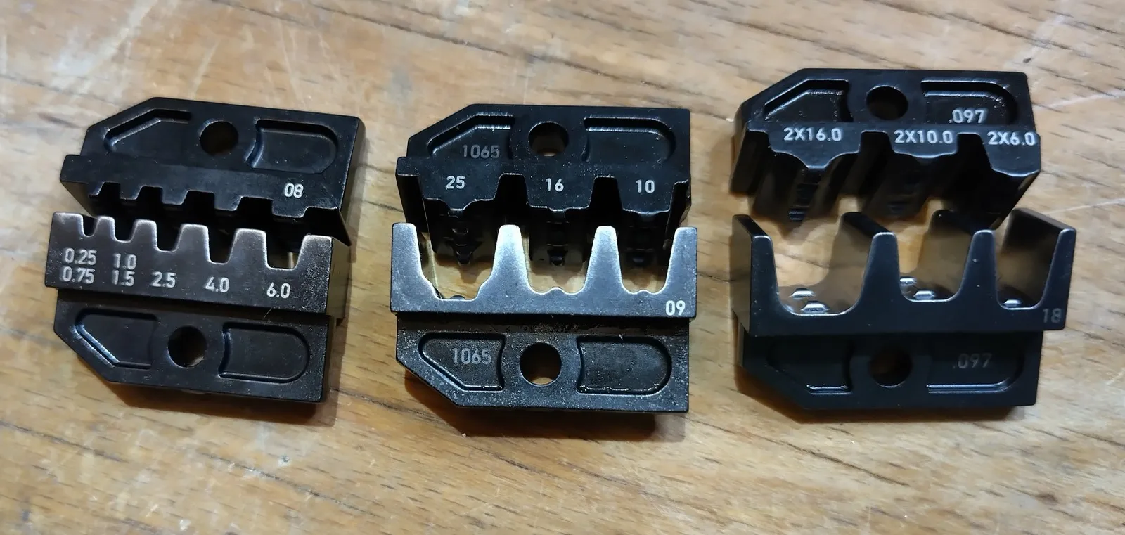
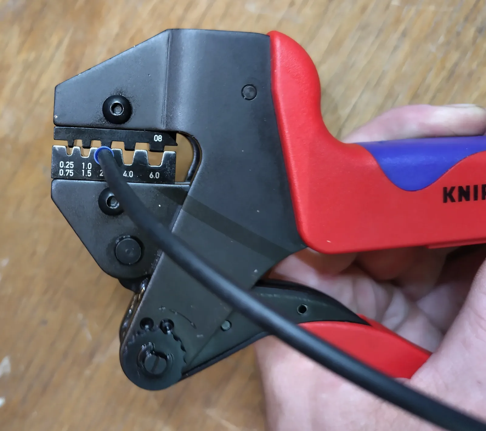
Dies 08, 09 and 18 side by side: everything from 0.25 mm² single conductors to TWIN 2x16 mm².
With the 97 43 200 A’s interchangeable head and three dies, you can cover pretty much every ferrule you’ll run into in a subdistribution board:
- Die 97 49 08 for 0.25 to 6 mm² single conductors
- Die 97 49 09 for 10, 16 and 25 mm² single conductors
- Die 97 49 18 for TWIN ferrules up to 2x16 mm²
For the 10 and 16 mm² TWIN work in this post you only need the last one, but if you’re buying a tool anyway, the full set pays off.
How to crimp it
Start by stripping both conductors to the same length, matched to the ferrule length. If bare copper sticks out past the ferrule, you either stripped too much or the ferrule is too short for the cross-section.
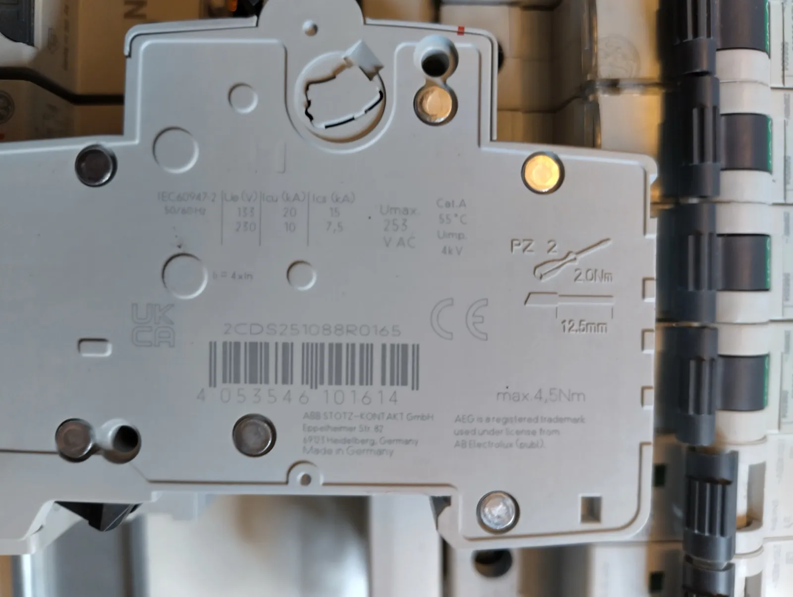
This breaker’s nameplate calls for a 12.5 mm strip length. But ferrules only come in 10, 12 or 18 mm, not 12.5 mm. My compromise: crimp onto the 12 mm ferrule and leave about 0.5 mm of bare copper showing in front of the insulation collar, rather than jump up to the noticeably longer 18 mm ferrule.
Next, push both conductors into the ferrule to the same depth, until the insulation collar sits flush against the conductor. This is where TWIN crimps most often go wrong: if one conductor sits even a millimeter shorter than the other, it ends up carrying less of the load later and can work loose under vibration.
Position the crimp head at a right angle and, if your pliers take interchangeable dies, pick the right TWIN die in the matching size. Then squeeze all the way through until the ratchet releases on its own. Opening it early almost always leaves you with an incomplete crimp, even if it looks finished from the outside.
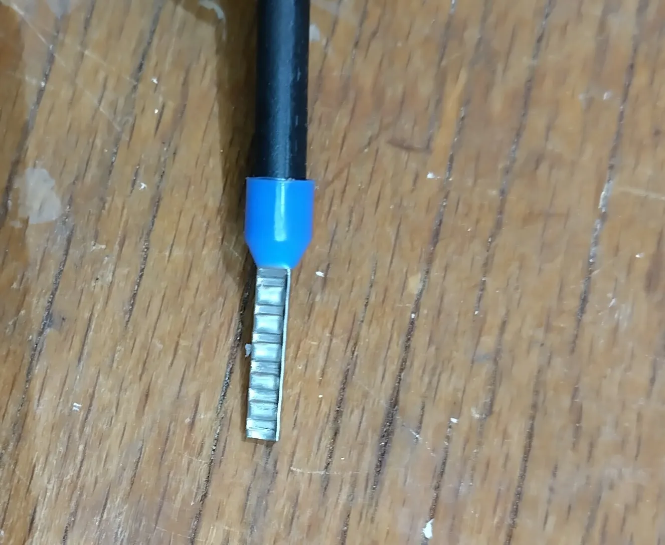
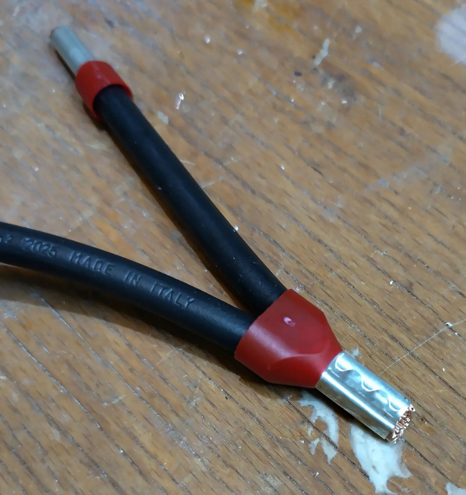
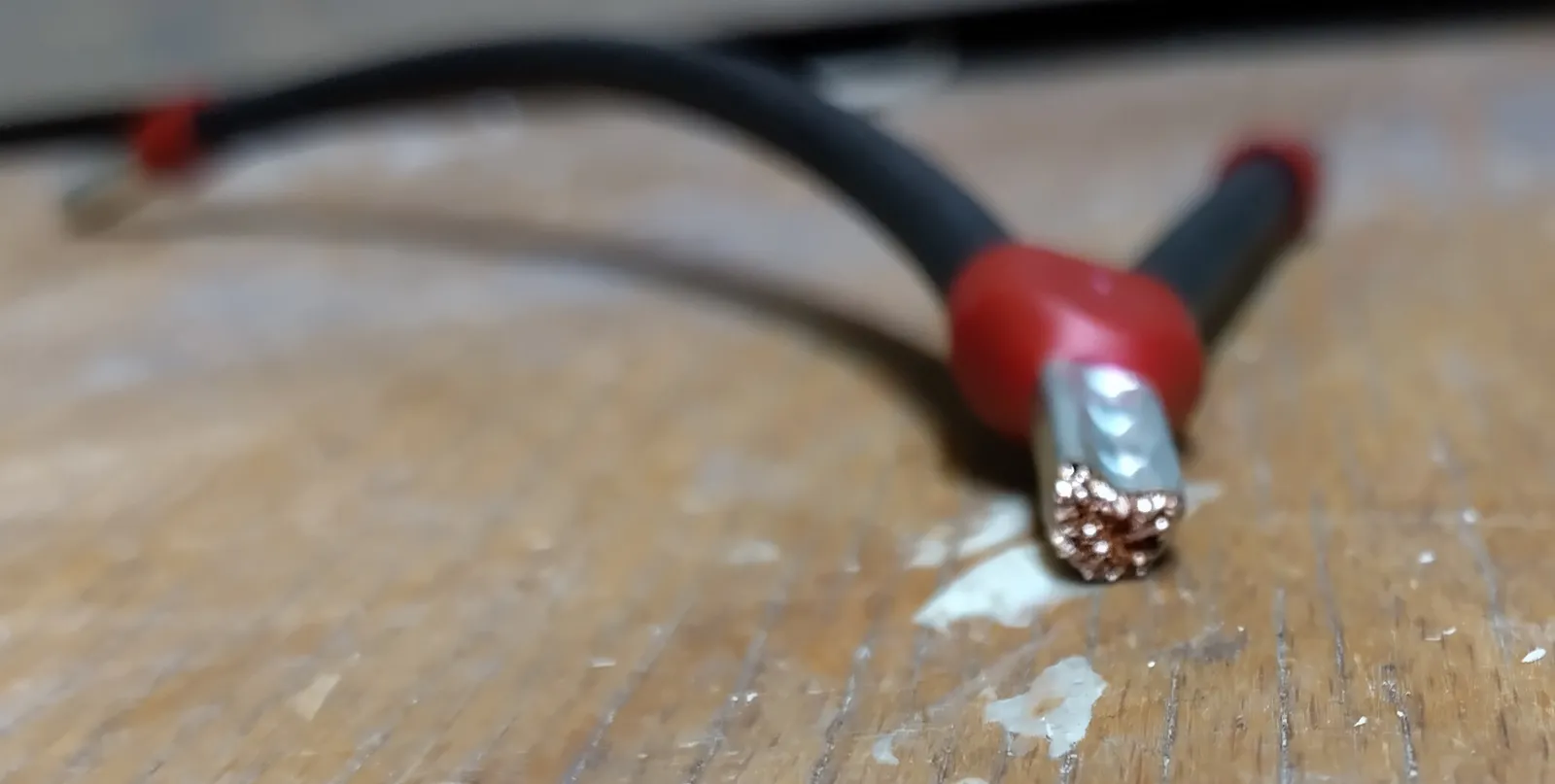
Finally, take a quick look: no burr on the ferrule, no loose strands sticking out the side, and both conductors visible the same distance at the back end. If one conductor noticeably wiggles while the other sits tight, the crimp wasn’t good. New ferrule, start over.
Common mistakes
The classic mistake is the wrong tool: the ferrule fits between the jaws geometrically, but the profile doesn’t press evenly across the surface. The second is uneven insertion depth between the two conductors. The third is stripping too little insulation, so the ferrule ends up seated on bare wire instead of resting on the insulation, which leads to it tearing out under tension.
The thick-cable paradox: why better copper makes for worse crimps
The thicker the cable, the more play the conductor has inside the ferrule.
The ferrule and the tool aren’t the only things that decide crimp quality. The quality of the conductor itself matters too, and that part catches people off guard. Buy a cable labeled “50 mm²” and you’re not necessarily getting 50 square millimeters of copper: manufacturers don’t have to deliver a specific amount of material for a nominal cross-section, only hit a defined electrical conductance.
The physics behind it: ohms per kilometer
The governing cable standard (IEC 60228 / VDE 0295) doesn’t define conductors by their raw geometry. It defines them by the maximum allowed electrical resistance over 1000 meters, given in ohms per kilometer ().
Conductor resistance follows a classic formula from electrical engineering:
Here is the total resistance, (rho) is the material’s resistivity, is the length (our 1000 meters), and is the actual cross-section.
Let’s stick with our 50 mm² cable: the standard requires that, in flexible class 5, it has a resistance of at most . Copper quality and metallurgical purity in production have kept improving over the decades. Today’s copper simply conducts better, and its resistivity has dropped.
Better copper saves material
Rearrange the formula for the cross-section and the problem shows up:
If the copper conducts better by nature, meaning a smaller , the manufacturer can shrink the actual physical cross-section and still hit exactly per kilometer. The standard is satisfied. On paper it’s still nominally 50 mm², but under the insulation there might only be 44 or 45 mm² of actual copper.
The air inside the ferrule
The electrons don’t care, the resistance checks out fine either way. But the crimping tool and the ferrule are mechanical parts, and this bothers them quite a bit. A 50 mm² ferrule is sized for exactly 50 mm² of material. If a few square millimeters are missing, something else fills that space: air.
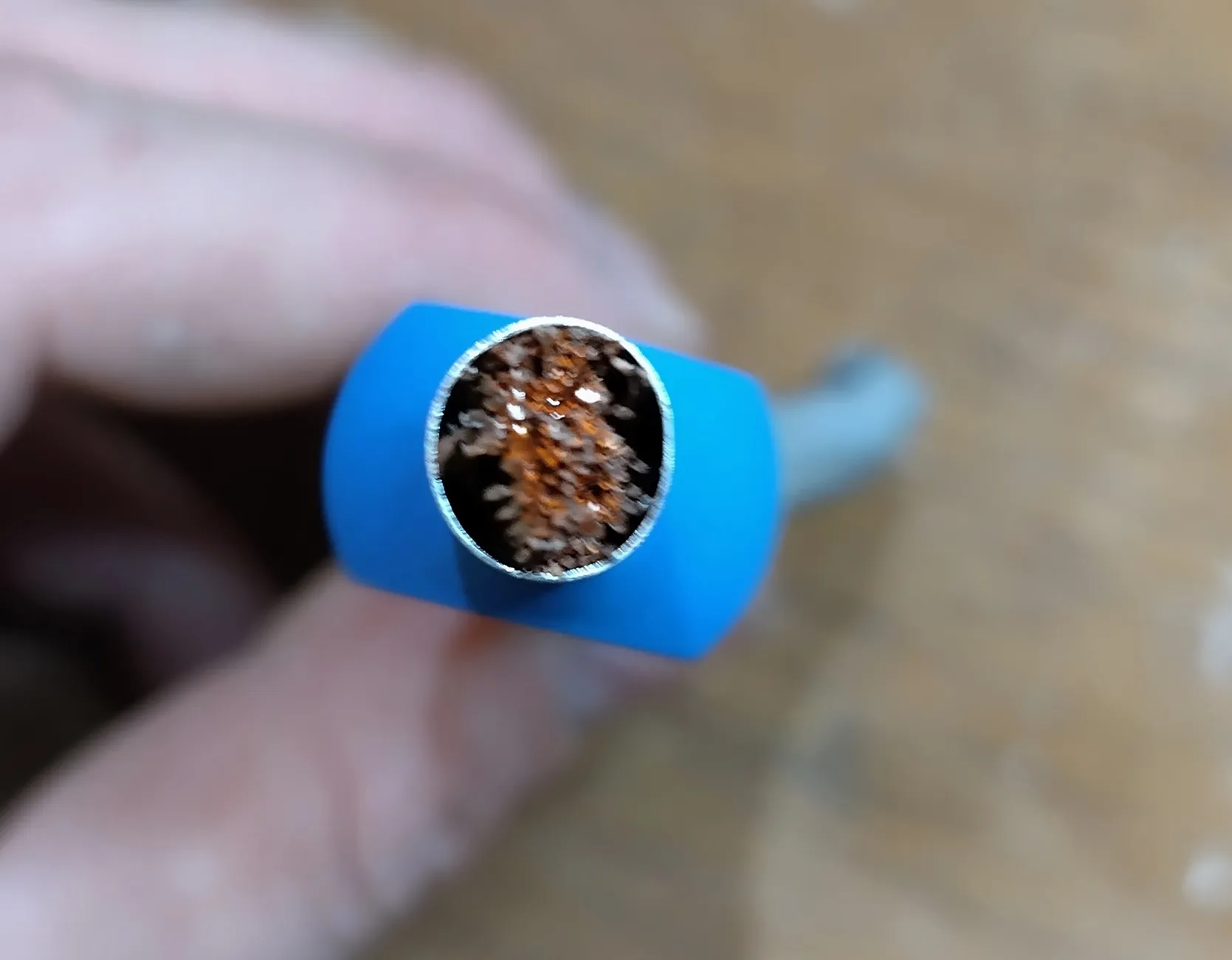
How much air remains between the strands depends on the cable itself too, not just on the crimping force.
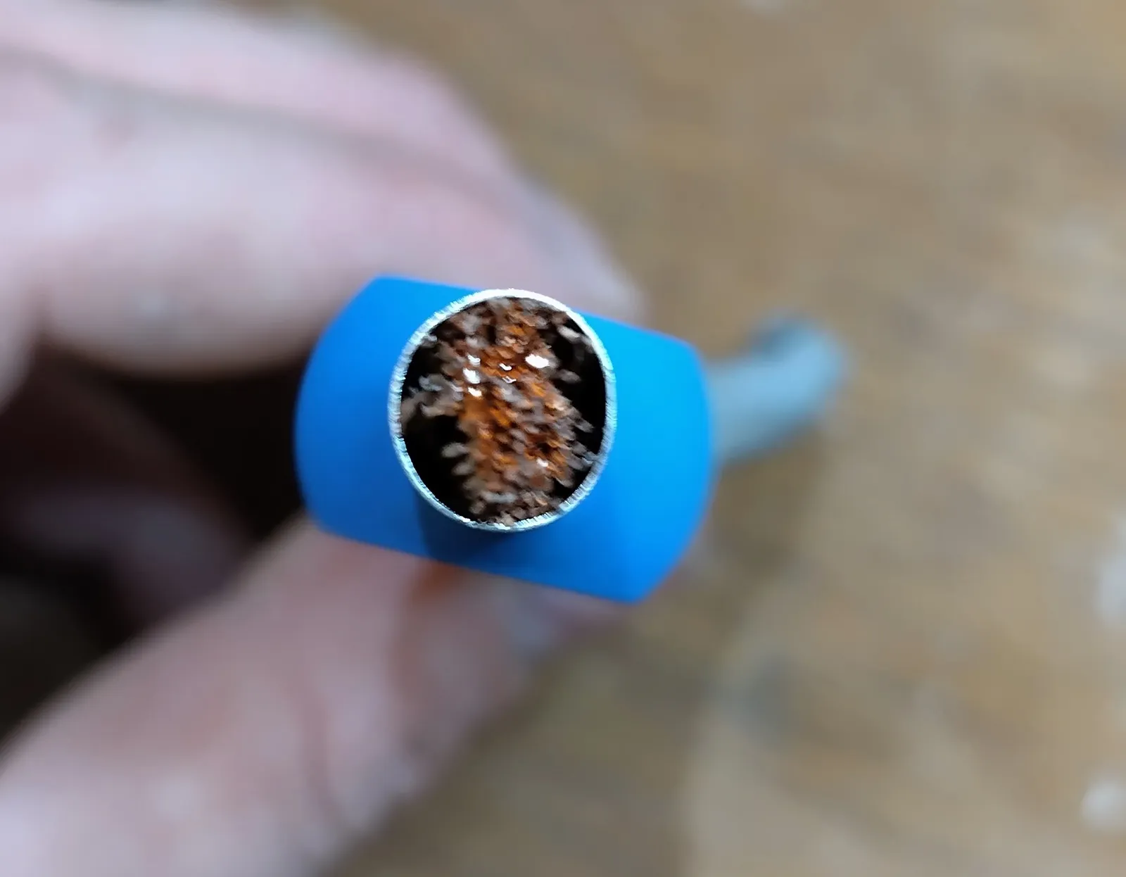
At small cross-sections like 1.5 mm², that missing fraction barely registers. At 50 or 70 mm², though, you can see it with the naked eye: the strands no longer fill the ferrule snugly, they have noticeable play.
The missing mass means the crimp can’t compress properly. Air pockets in the crimp drive up the contact resistance right at the connection point, which partly cancels out the hard-won benefit of that high-purity copper. In the worst case, the ferrule doesn’t build up enough mechanical pressure at all: the conductor doesn’t sit tightly enough and pulls out under tension instead of holding securely for the long haul.
A word on the standard
Insulated ferrules are standardized under DIN 46228-4, including a color code by cross-section. Still, for work in a permanent electrical installation, the bottom line stays the same: if you’re not sure whether your tool and ferrule are approved for the application, ask a qualified electrician or check the ferrule’s datasheet.
What this looks like in practice
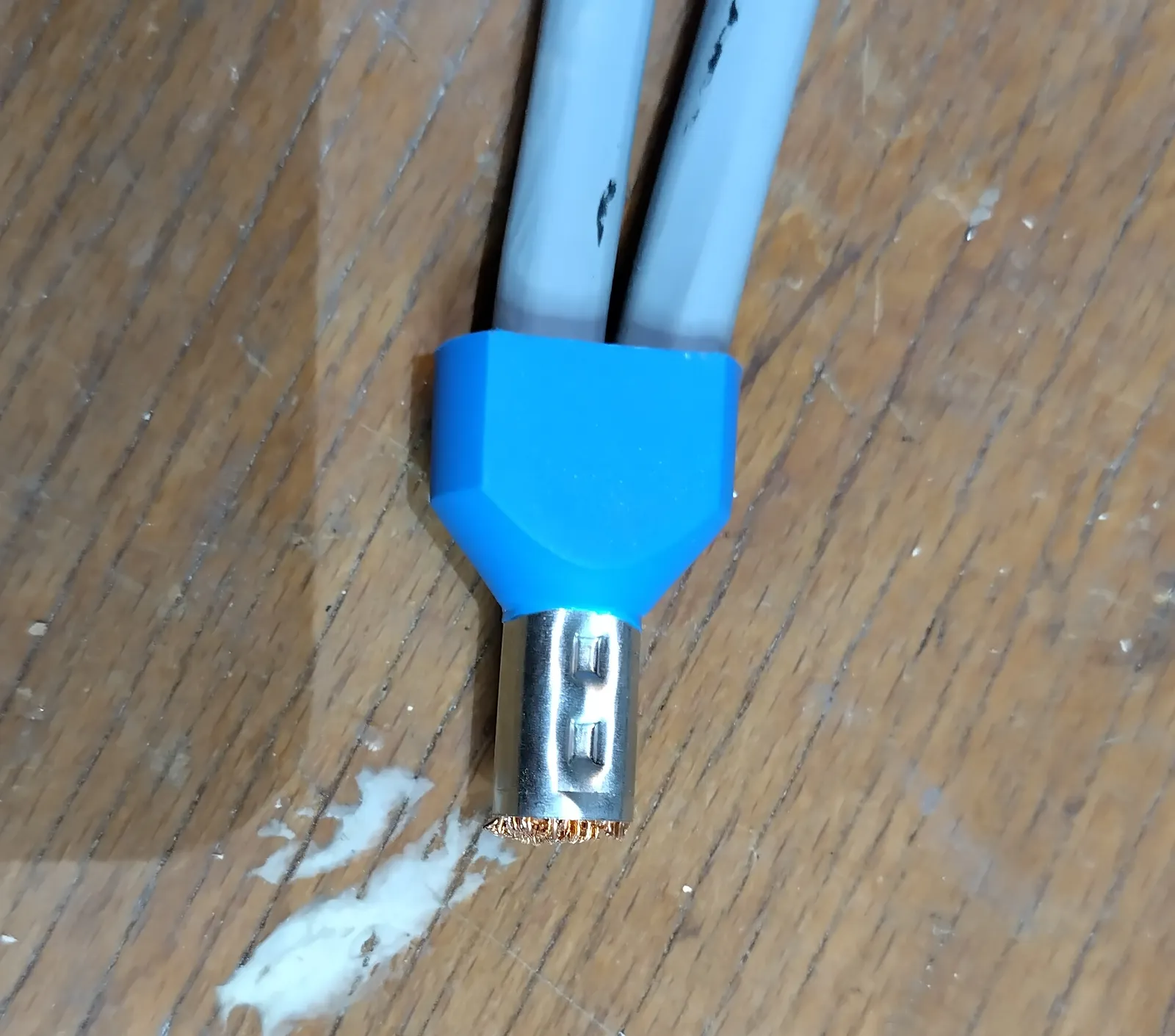
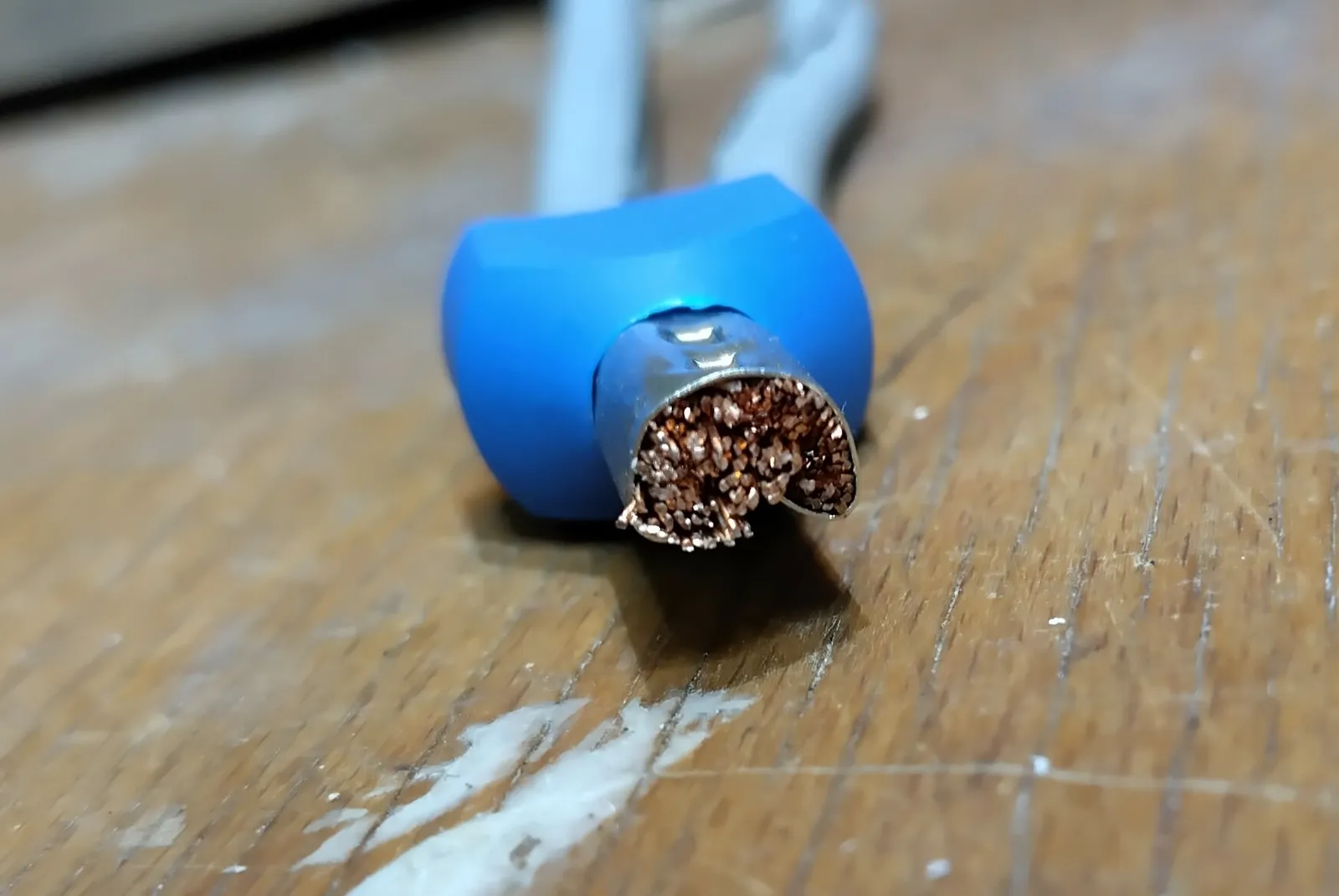
From 2.5 through 10 to 16 mm², single and TWIN, using the three interchangeable dies of the Knipex 97 43 200 A.
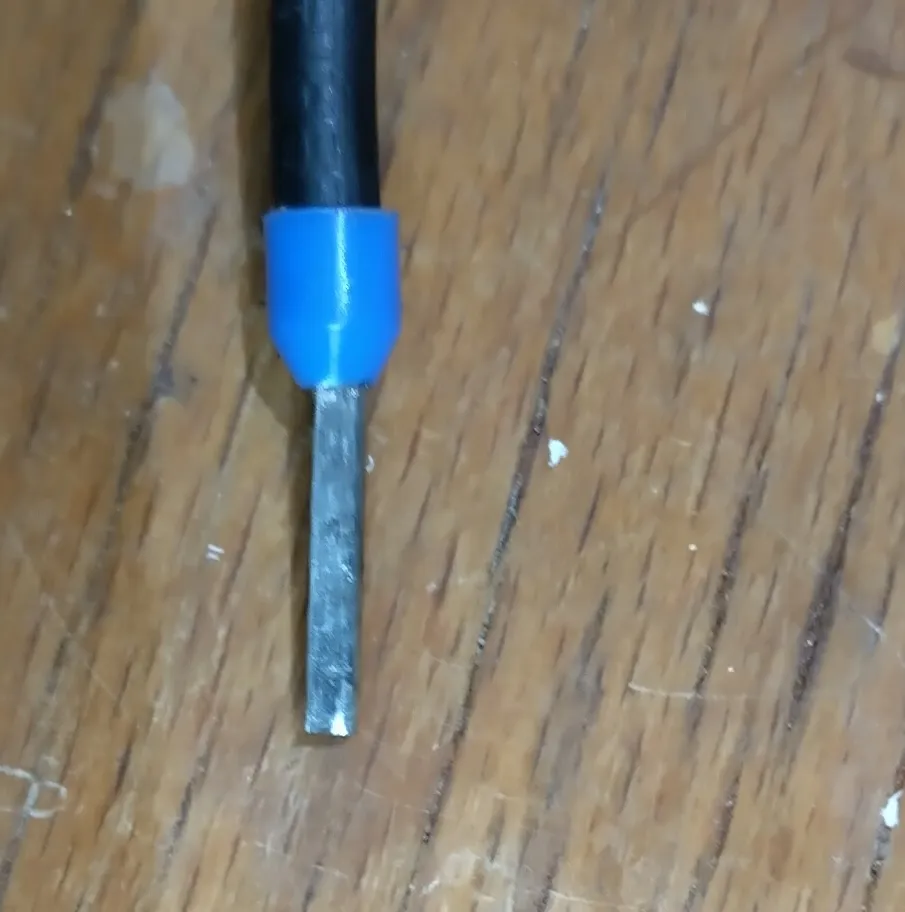
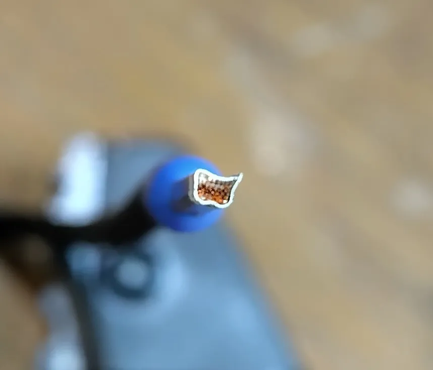
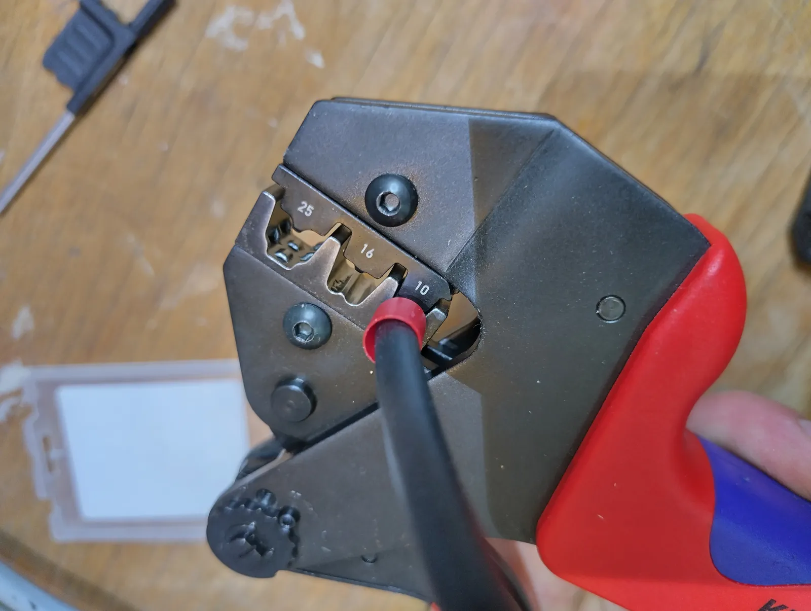
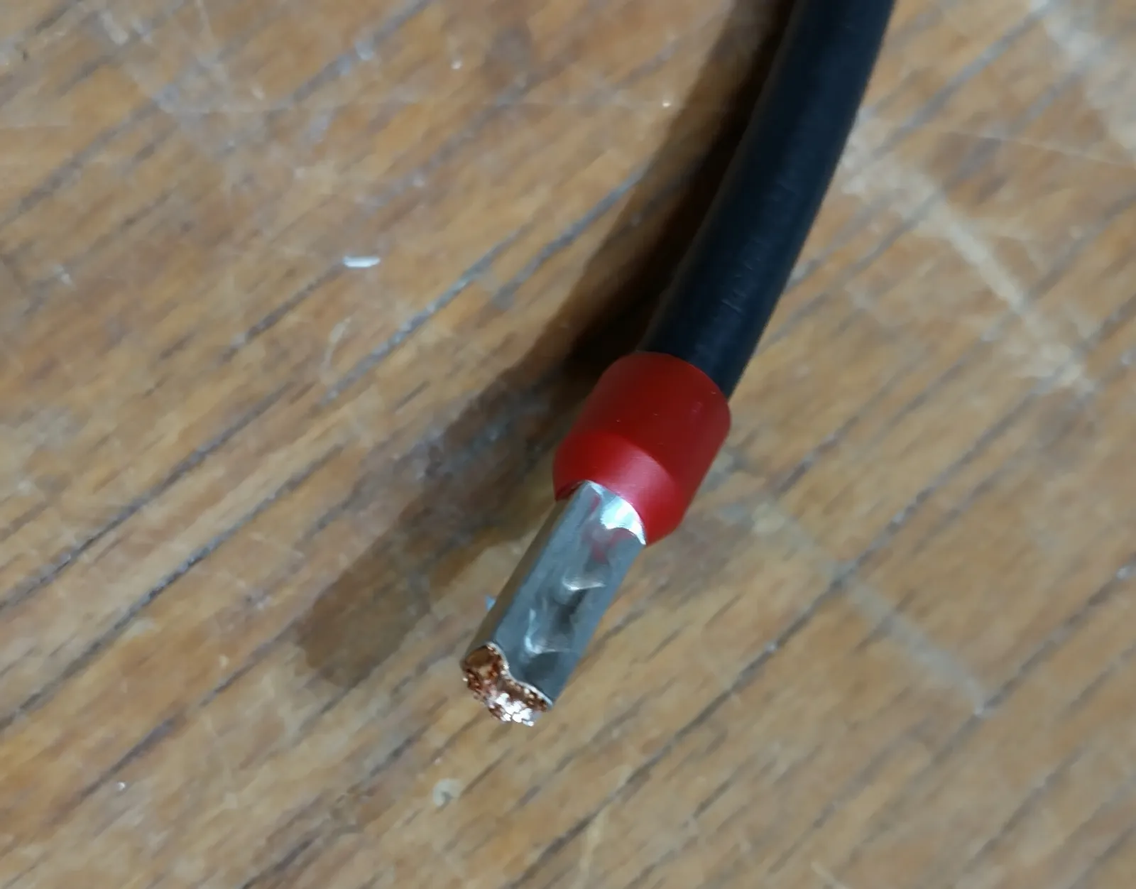
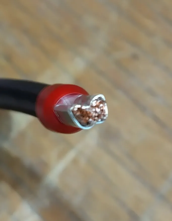
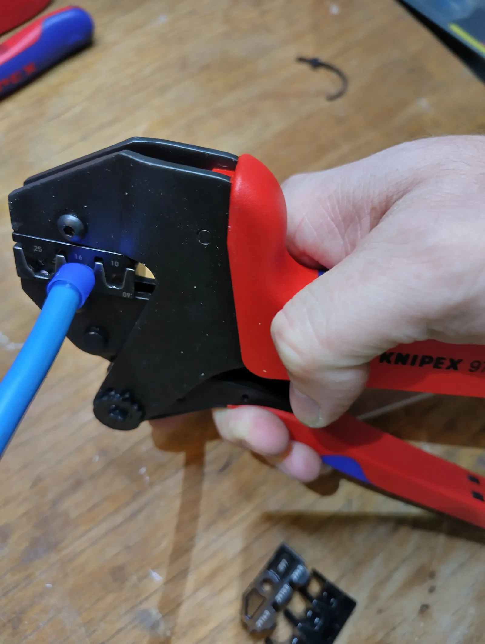
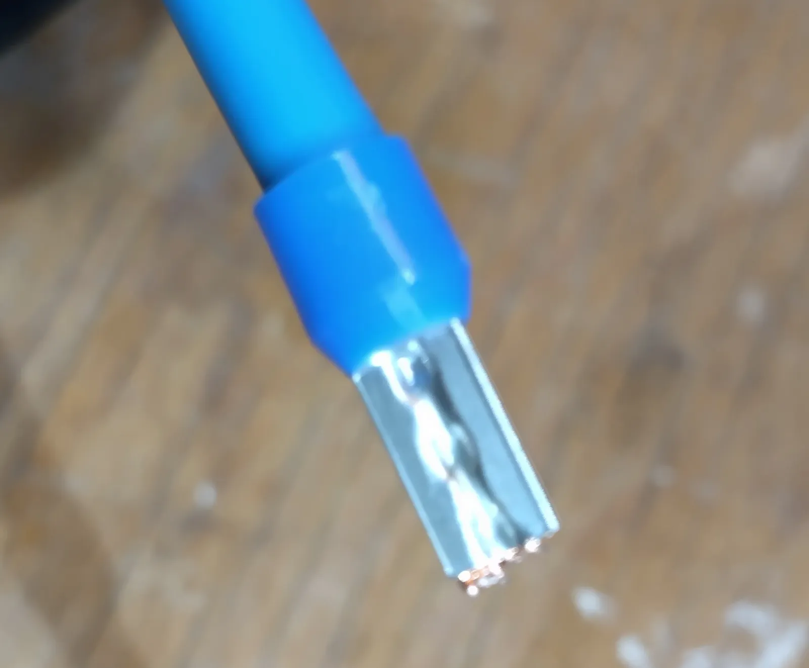
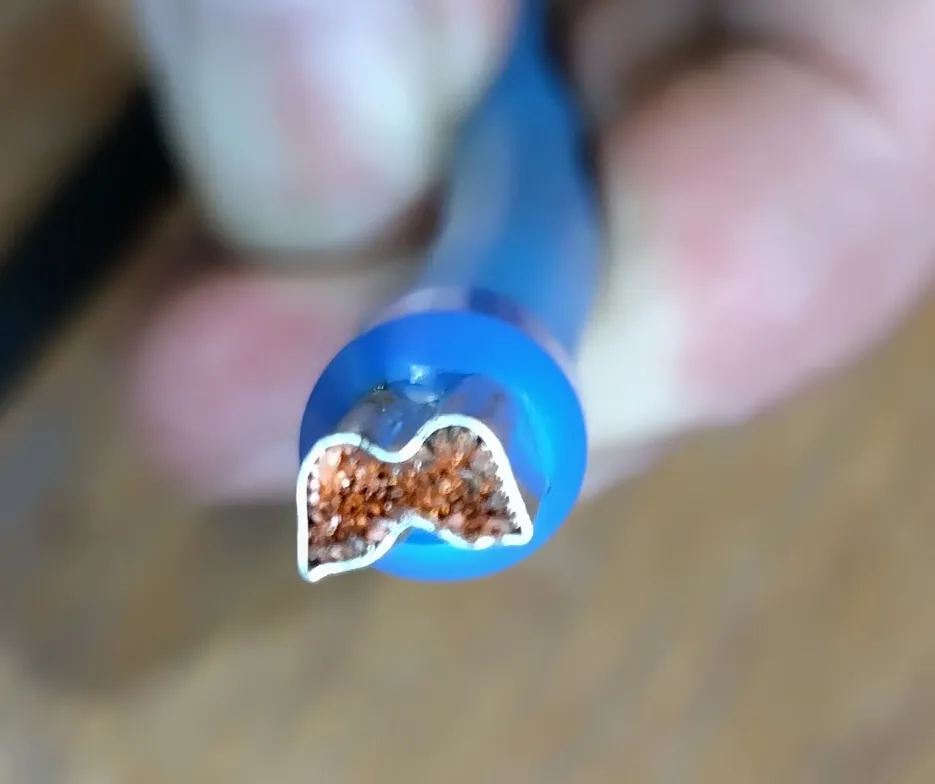
The next post covers the ferrules themselves: what length you need, and how to tell good stock from bad.
Affiliate disclosure: this post contains Amazon affiliate links. As an Amazon Associate I earn from qualifying purchases. If you buy through one of these links, I get a small commission and you pay the same price.
Comments
Write a comment